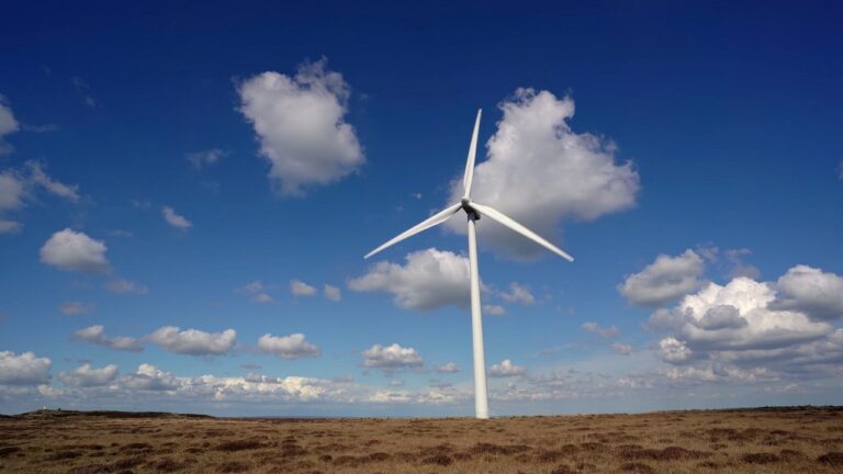
Horizontal-axis wind turbine systems convert wind energy into electricity by rotating blades around a shaft aligned parallel to the ground. Aerodynamic shaping and directional alignment allow a horizontal-axis wind turbine to capture energy efficiently as airflow moves across the rotor.
Airflow interaction with blade surfaces initiates rotational motion through lift forces that produce continuous rotation. Horizontal-axis wind turbine technology dominates modern wind power generation due to its scalability and suitability for large-scale installations.
Operating principles described here lead to a more detailed discussion of structure, energy conversion, and control systems.
The Basic Working Principle
A horizontal axis wind turbine captures wind energy through blades mounted on a rotor connected to a central shaft aligned parallel to the ground. Airflow over the blade surfaces generates lift in a manner similar to aircraft wings, causing continuous rotational motion.
Blade geometry, pitch angle, and rotational speed are designed to maximize lift while minimizing drag under typical operating conditions.
Orientation relative to wind direction distinguishes a horizontal axis wind turbine clearly when compared to a vertical axis wind turbine.
Vertical axis wind turbine designs can accept wind from any direction due to their vertical shaft arrangement, while a horizontal axis wind turbine must face the incoming wind to operate efficiently.
Active yaw systems rotate the nacelle so the rotor remains aligned with changing wind direction, maintaining stable power output.
Rotational motion produced at the rotor is transferred through the main shaft to components housed inside the nacelle. In most large turbines, rotational speed increases significantly before electricity generation occurs.
Typical operating characteristics include the following values, which define this conversion stage:
- Rotor rotation speeds commonly range between 10 and 20 revolutions per minute
- Gearbox output speeds typically rise to approximately 1,000–1,800 revolutions per minute
Mechanical energy is then converted into electrical energy by the generator through electromagnetic induction. Power conditioning equipment regulates voltage and frequency before electricity is delivered to the grid, completing the basic working cycle of a horizontal-axis wind turbine.
In short:
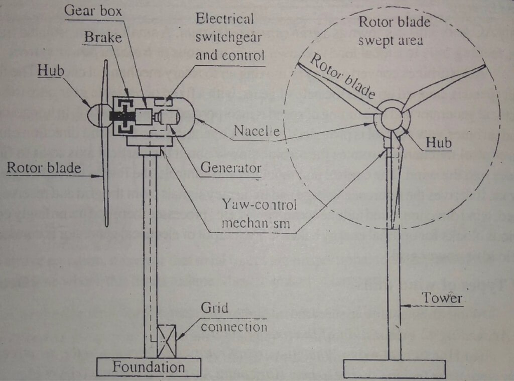
Key Components and Their Roles
Part
Function
Act
Blades
Capture wind energy
Airfoil shape, 2–3 units
Hub
Connects blades
Transfers rotation
Shaft
Transmits motion
Bearing supported
Gearbox
Increases speed
~15 rpm to ~1,500 rpm
Generator
Produces electricity
Electromagnetic induction
Nacelle
Houses components
Mechanical enclosure
Yaw System
Aligns with wind
Motor controlled
Tower
Supports turbine
Tall steel or concrete
Control System
Regulates operation
Monitors conditions
Modern wind turbines rely on a coordinated set of mechanical, electrical, and control elements that work together to convert moving air into usable electricity. Each component contributes a specific function, and performance depends on how effectively these parts interact under varying wind and load conditions.
Blades
Blades carry responsibility for initiating energy conversion by interacting directly with wind. An airfoil profile generates lift as airflow moves across curved surfaces, creating rotational force that powers the turbine. Design decisions aim to maximize energy capture while keeping structural loads manageable.
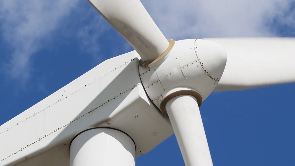
Hub
Hub forms the mechanical link between blades and the rest of the drivetrain. Rotational forces collected by blades pass through this component before reaching internal systems. Constant exposure to variable wind loads places stress on connections, so alignment and material strength receive careful consideration during engineering and assembly.
Shaft
Shaft transmits rotational motion generated at the rotor into the power conversion system. Bearings support continuous rotation while reducing friction and heat buildup. Two distinct rotational stages often operate together, allowing efficient motion transfer across different speed requirements without excessive mechanical strain.
Gearbox
Gearbox performs speed conversion that prepares rotational motion for electricity generation. Rotor movement occurs slowly, making speed amplification essential before interaction with electrical equipment.
Generator
Generator produces electrical energy by converting mechanical rotation into alternating current through electromagnetic induction. Magnetic fields interact with conductive coils as the shaft rotates, creating voltage suitable for transmission. Configuration varies based on turbine capacity, efficiency targets, and maintenance expectations.
Nacelle
Nacelle encloses critical equipment such as gearbox, generator, and control hardware within a protective structure. External design shields components against weather exposure, while internal layout supports safe inspection and servicing. Accessibility influences downtime and long term operational reliability.
Yaw System
Yaw system ensures consistent alignment between turbine orientation and wind direction. Continuous adjustment allows blades to face airflow efficiently as conditions change.
Tower
Tower raises the turbine to elevations where wind speeds remain stronger and less turbulent. Structural design resists bending forces caused by wind and rotor mass while maintaining stability over long service periods. Construction materials typically include steel or reinforced concrete, selected according to height and site requirements.
Control System
Control system manages turbine operation by coordinating sensors, software, and actuators. Real time data analysis supports efficiency while protecting equipment under extreme conditions.
The Aerodynamics Behind the Spin
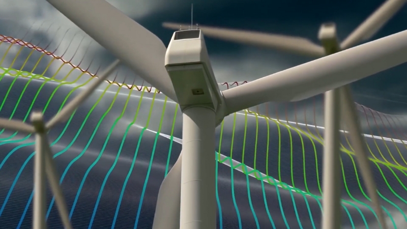
Aerodynamic design plays a key role in how a horizontal-axis wind turbine captures wind energy. Blades are shaped as airfoils, thicker at the root and thinner near the tip, with a twisted profile that helps maintain efficient airflow and lift along the entire length of the blade.
The goal of this shaping is to maximize lift relative to drag so that the turbine can convert more of the wind’s kinetic energy into rotational motion rather than losing it to resistance.
Airflow over curved blade surfaces produces pressure differences between opposite sides of each blade, generating lift that causes the rotor to rotate.
Lift-based blade design allows a horizontal axis wind turbine to extract substantially more energy than drag-based systems, since lift grows with rotational speed while drag restricts efficiency.
The turbine must operate within specific wind speed limits:
Wind Speed Range
Turbine Response
0–3 m/s (Cut-in)
Turbine remains idle; wind is too weak.
3–12 m/s (Optimal)
A turbine generates electricity efficiently.
12–25 m/s (Rated Power)
The turbine produces maximum output.
>25 m/s (Cut-out)
Automatic shutdown to prevent damage.
Safe and stable operation requires control within defined wind speed limits. Rising wind speed above the rated value triggers pitch control, which adjusts blade angle relative to incoming airflow.
Blade pitch adjustment limits rotational speed, stabilizes power output, and prevents mechanical overload.
Regulation of aerodynamic forces reduces stress on the drivetrain and generator, extending component life.
Correct blade pitch positioning maintains balance between energy capture and structural protection, allowing consistent performance under varying wind conditions while preserving operational safety.
The Role of the Gearbox and Generator
Power produced by a horizontal-axis wind turbine depends on matching two very different rotational requirements. Rotor blades turn slowly to maximize aerodynamic efficiency, while electrical generators require much higher rotational speeds to produce grid-compatible electricity. For this reason, most horizontal-axis wind turbine designs rely on a gearbox placed between the main shaft and the generator.
Speed conversion inside a conventional drivetrain can be illustrated using typical operating values:
- Rotor rotation commonly occurs around 10–20 revolutions per minute
- Generator operation is optimized near 1,000–1,800 revolutions per minute
Gearboxes increase rotational speed through multiple gear stages while transferring torque efficiently. This allows standard generators to operate at their optimal electrical frequency without requiring excessively large components.
However, gearboxes introduce mechanical complexity, friction losses, and wear, making them one of the most maintenance-intensive parts of a wind turbine.
An alternative approach appears in direct drive horizontal axis wind turbine systems, which eliminate the gearbox entirely. Instead of increasing speed mechanically, these turbines use large-diameter generators designed to operate efficiently at low rotational speeds.
Direct drive designs reduce the number of moving parts and lower mechanical stress, improving reliability and reducing servicing requirements.
Trade-offs associated with direct drive systems arise due to generator construction requirements:
- Larger generators increase nacelle mass
- Strong permanent magnets and advanced materials raise manufacturing costs
Choice between gearbox-based and direct drive configurations depends on turbine size, location, maintenance strategy, and long term operating costs, making drivetrain design a key engineering decision in horizontal axis wind turbine development.
Yaw and Pitch Control Systems
Wind direction changes continuously, and efficient operation requires a horizontal-axis wind turbine to remain aligned with incoming airflow. Misalignment reduces aerodynamic performance and increases uneven loading on blades and structural components, making active control essential for sustained power generation.
Yaw control manages the horizontal orientation of the turbine by rotating the nacelle at the top of the tower. Sensors measure wind direction and send signals to electric motors that turn the nacelle so the rotor faces directly into the wind.
Accurate yaw alignment minimizes energy losses and prevents asymmetric forces that could accelerate mechanical wear.
Typical yaw systems operate within defined limits to avoid excessive movement during turbulent conditions:
- Yaw motors rotate the nacelle slowly to reduce structural stress
- Wind direction sensors provide continuous feedback for alignment
Pitch control operates simultaneously by adjusting the angle of each blade relative to the wind. Small pitch changes regulate aerodynamic lift, allowing precise control of rotor speed and power output.
During strong winds, blades rotate slightly out of the wind to limit lift and prevent overspeed, while lower wind speeds allow angles that maximize energy capture.
Power Conversion and Grid Integration
Electricity produced by a horizontal-axis wind turbine generator appears as alternating current with variable voltage and frequency due to changing wind speed and rotor motion.
Direct connection to the electrical grid is not possible under these conditions, since grid infrastructure requires stable frequency and controlled voltage levels.
Power electronics inside the turbine handle this mismatch. Conversion begins immediately after generation and follows a defined sequence that prepares electricity for safe and reliable transmission.
Key stages in this process involve frequency stabilization, voltage regulation, and synchronization with grid standards:
Step
Process
Output
1
The generator produces AC at a variable frequency
10–1000 Hz
2
A rectifier converts AC to DC
Stable DC current
3
Inverter converts DC back to grid-frequency AC
50 or 60 Hz
4
A transformer increases voltage for transmission
690 V → up to 33 kV
Power converters ensure consistent electrical quality despite fluctuations in wind speed. Stable output protects grid infrastructure and allows wind energy to integrate smoothly with other generation sources such as thermal, hydro, or solar power plants.
Efficiency and Energy Output
View this post on Instagram
Energy conversion efficiency plays a central role in the effectiveness of a horizontal axis wind turbine. Under favorable wind conditions, modern turbines convert a significant portion of available wind energy into electrical power. Typical performance values approach theoretical aerodynamic limits defined by the Betz principle, which caps maximum extractable energy at 59.3 percent of wind kinetic energy.
Practical conversion levels usually fall within a narrower operating range that reflects mechanical losses, aerodynamic constraints, and electrical conversion limits:
Energy conversion efficiency commonly reaches 40%–50% under optimal conditions
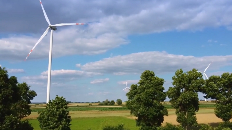
Power output scales strongly with turbine size and rotor diameter. Larger turbines access higher wind speeds at greater heights and sweep more air, resulting in substantially higher annual energy production.
Turbine Size
Rotor Diameter
Power Capacity
Annual Output (avg)
Small (Residential)
5–10 m
5–20 kW
Up to 40,000 kWh
Medium (Community)
30–50 m
250–500 kW
1–2 million kWh
Utility-Scale
100–160 m
2–6 MW
6–20 million kWh
Electricity generated at utility scale allows a single horizontal-axis wind turbine to supply power for thousands of households annually, depending on site wind conditions and capacity factor.
Advantages and Limitations
Widespread adoption of horizontal-axis wind turbine technology reflects strong performance, proven reliability, and compatibility with modern power grids. At the same time, engineering and environmental challenges influence site selection and project design.
Advantages
Limitations
High efficiency in consistent wind areas
Complex installation and maintenance
Mature, proven technology
Requires tall towers and strong foundations
Suitable for large-scale wind farms
Sensitive to turbulence in uneven terrain
Easier integration with existing grid systems
Visual and noise impact in some regions
Balanced assessment of these factors guides deployment decisions and supports continued development of horizontal axis wind turbine systems for large-scale renewable energy production.
Bottom Line
@arlogao Horizontal-axis wind turbines can operate in environments as cold as minus 40 degrees Celsius, requiring low wind speeds while delivering high output efficiency. Their power range from 1 kilowatt to 500 kilowatts makes them suitable for diverse applications.#windturbine #windpower #windfarm #freeenergy #newenergy ♬ C260(Lak House)(剪辑版) – Jamvana
Horizontal-axis wind turbine represents the culmination of decades of engineering, sleek, powerful machines that transform invisible air currents into tangible electricity. Their aerodynamic precision, advanced control systems, and scalability make them the backbone of modern wind energy production.
Whether onshore in the American Midwest or offshore in the North Sea, HAWTs are quietly redefining how the world produces power, one gust at a time.