Electric grids are being pushed harder than at any point in their history. Wind and solar capacity keep expanding, demand patterns feel sharper and less predictable, and tolerance for outages keeps shrinking.
Storage has quietly become the hinge that holds the whole system together, turning variable generation into electricity that operators can actually rely on.
Most conversations still default to lithium-ion batteries. They respond fast and work well for short bursts. Trouble appears when power needs stretch past a few hours, or when weather patterns linger.
A long winter calm with weak wind, a cloudy heat wave, or a regional storm can expose a gap that short-duration storage cannot cover.
That gap is where long-duration energy storage starts to matter. The U.S. Department of Energy frames long-duration storage as a core enabler for clean, resilient grids, with its Long Duration Storage Shot focused on cutting the cost of 10+ hour storage by 2030.
Liquid energy storage has moved into that conversation as a serious contender, not a theoretical one.
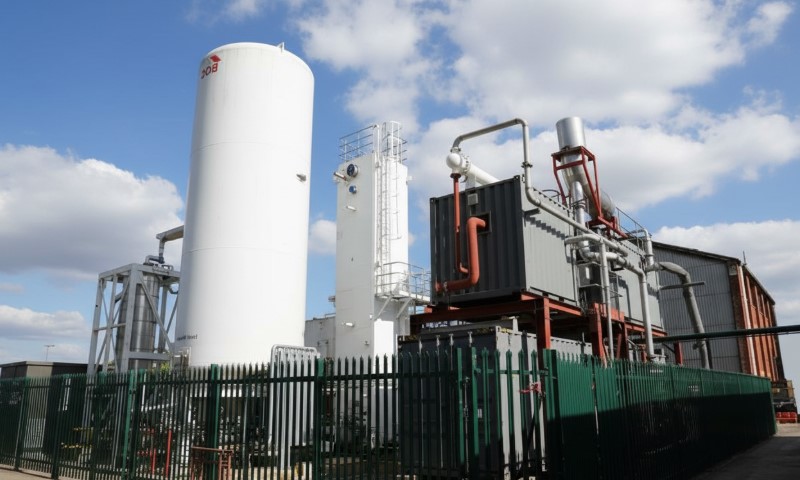
Liquid systems approach storage with an industrial mindset. Electricity goes in, a liquid state holds energy, and power comes back out when the grid asks for it. No lithium, no cobalt, no mountain reservoirs.
Just tanks, compressors, heat exchangers, and physics that utilities already know how to operate.
What Liquid Energy Storage Means on the Grid
Liquid energy storage refers to power-to-power technologies where electricity is converted into a liquid form during charging, then converted back into electricity during discharge.
Two families dominate current deployments and planning:
- Liquid Air Energy Storage, often shortened to LAES or called cryogenic energy storage
- Liquid CO2 systems, frequently described as Carnot batteries or CO2 Batteries
Both behave like reversible power plants. They store energy as pressure, temperature, and phase change rather than chemistry.
On the grid, they compete in the long-duration zone where energy capacity matters as much as power capacity. Scaling does not mean stacking more battery modules. Developers add tank volume, thermal storage, or both.
Liquid storage tends to shine in roles such as:
- Multi-hour shifting, including evening ramps and daily solar balancing
- Daily to weekly grid balancing
- Capacity and reliability support in renewable-heavy regions
- Flexible siting near substations or load centers
Liquid Air Energy Storage, The Core Idea
Liquid Air Energy Storage stores electricity by turning ambient air into a cryogenic liquid, holding it in insulated tanks, then expanding it back to drive a turbine.
The International Energy Agency Energy Storage TCP factsheet outlines the process clearly.
During charging, air is refrigerated to about -190°C until it liquefies. During discharge, that liquid air is pumped to high pressure, warmed through heat exchange, and expanded through a turbine to generate electricity.
Cold recovered during expansion can be stored and reused later, reducing the energy needed for future liquefaction.
A helpful way to picture LAES is as a grid-scale cold economy machine. Electricity buys cold. Cold holds energy. Heat unlocks power.
LAES Step By Step, Charging, Storage, And Discharge
@curiosityaihub Scientists are freezing air to minus 196°C and turning it into massive energy storage systems! Liquid Air Energy Storage works by cooling regular air until it becomes liquid, storing it in giant insulated tanks, then expanding it 700 times to spin turbines when power is needed. Highview Power’s breakthrough system delivers 50 MW with 250 MWh storage capacity using zero lithium, cobalt, or rare earth materials. The technology can store renewable energy for days or weeks, offering 50-60% round-trip efficiency with 30+ year operational life. Unlike chemical batteries, LAES systems use abundant atmospheric air and proven industrial equipment. When integrated with waste heat from nearby facilities, efficiency increases significantly, making this a viable solution for grid-scale renewable energy storage. This mechanical storage approach could solve intermittency challenges for wind and solar power, providing reliable backup without environmental concerns of mining rare materials. Could frozen air be the key to 100% renewable electricity grids? #LiquidAirEnergyStorage #FrozenAirBattery #EnergyStorage #RenewableEnergy #CleanTech ━━━━━━━━━━━━━━━━━━━━━━━━━━━━━━━━━━━━━━━━ 🔗 CURIOSITY AI – Your Science & Tech Hub 💝 SUPPORT OUR MISSION: ❤️ Patreon: patreon.com/CuriosityAI ☕ Ko-fi: ko-fi.com/CuriosityAI 🌐 EXPLORE MORE: 📖 Blog: curiosityaihub.com 📕 AI Automation Ebook: sorinciovica.gumroad.com/l/jzhuxh 📱 FOLLOW US: 🎵 TikTok: tiktok.com/@curiosityaihub 📷 Instagram: instagram.com/curiosity_ai_hub 🐦 X: x.com/curiosityaihub 👥 Facebook: facebook.com/curiosityaihub 🛠️ RECOMMENDED TOOLS: 🎥 Fliki (20% OFF): https://fliki.ai/?via=curiosityai 📹 Pictory (20% OFF): https://pictory.ai?ref=curiosityai 🎭 Synthesia: https://www.synthesia.io/?via=curiosityai
LAES operates as a continuous thermodynamic cycle where electricity is converted into stored cold during charging, held safely in liquid form, and later released through controlled expansion to deliver power back to the grid.
Charging, Turning Electricity Into Cryogenic Liquid
The process starts with air intake, filtration, and drying. Compressors and expansion stages then cool the air aggressively until it liquefies around -190°C.
Liquefaction is energy-intensive. System performance depends heavily on how well compression heat and expansion cold are captured and reused. Efficient thermal integration often separates a strong design from an expensive one.
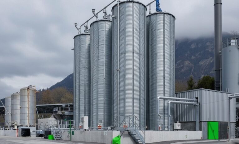
Storage, Low-Pressure Cryogenic Tanks
Liquid air is stored at low pressure inside insulated cryogenic tanks.
From a grid planning perspective, scalability is a major advantage. Increasing storage duration often means adding tank volume or thermal storage rather than rebuilding the entire plant.
Discharge, Pumping, Heating, And Expansion
When power is needed:
- Liquid air is pumped to about 100–150 bar
- Heat exchangers warm it toward ambient temperature
- High-pressure air expands through a turbine or expander
- Electricity flows back to the grid
Pumping a liquid takes far less energy than compressing a gas, which helps offset some efficiency losses earlier in the cycle.
LAES Performance, What The Numbers Look Like
According to the IEA Energy Storage TCP factsheet, real-world LAES expectations fall into a well-defined range.
| Metric | Typical Values |
| System efficiency | 50–65% |
| Storage duration | Hours to days |
| Response time | Minutes |
| Service life | ~30 years |
| Cycle life | ~20,000 cycles |
| Energy density | ~60–230 kWh/m³ |
| Loss per time | 5–15% per month |
That monthly loss rate pushes LAES toward daily or weekly operation rather than seasonal storage. Designs optimized for frequent cycling perform best.
Typical LAES Plant Sizing
The same IEA factsheet lists feasible plant sizes squarely in utility territory.
- Energy capacity: 50–5,000 MWh
- Power output: 25–600 MW
Those numbers place LAES alongside peaker replacement, renewable firming, and regional balancing assets.
LAES Cost, A Reality Check From MIT
A 2025 analysis from the Massachusetts Institute of Technology modeled future U.S. grid scenarios and evaluated the levelized cost of storage for LAES.
The model produced an LCOS of around $60 per MWh for liquid air storage.
MIT reported that figure as roughly one-third of lithium-ion storage and about half of pumped hydro under their modeled assumptions.
A 100 MW LAES system served as the reference size, and capital subsidies in the 40%–60% range significantly improved deployment economics in decarbonization scenarios.
Cost results always depend on assumptions, but the takeaway is clear. Once the duration stretches beyond a few hours, LAES follows a different cost curve than lithium-ion systems.
Real LAES Projects, From Pilot To Commercial Scale
Liquid air storage has crossed the line from theory into steel and concrete.
Milestones listed by the IEA include:
- 350 kW / 2.5 MWh pilot plant tested from 2010–2013
- 5 MW / 15 MWh pre-commercial plant near Manchester tested from 2015–2020
- A 50 MW / 300 MWh commercial plant reported as under construction, targeting completion in 2026
That 50 MW / 300 MWh scale firmly places LAES in the utility asset category rather than experimental infrastructure.
Why LAES Makes Sense For The Grid
LAES aligns well with modern grid needs by offering long-duration energy shifting, flexible siting, and infrastructure-scale reliability that fits naturally into utility operations.
Long Duration Without Geography Limits
Pumped hydro remains mature and proven, but geography limits expansion. MIT highlights siting constraints as a major bottleneck.
LAES can be built near cities, substations, or retiring thermal plants without relying on mountains or large elevation differences.
Better Alignment With 8+ Hour Needs
MIT notes lithium-ion systems are often economical for about 4 hours. Beyond that point, scaling costs rise quickly.
LAES targets the duration range where grids begin needing sustained output across an evening peak, overnight lull, or multi-day imbalance.
Grid Services Beyond Energy Shifting
Many LAES designs rely on rotating machinery such as turbines and compressors. Depending on interconnection and controls, that equipment can support grid services beyond simple arbitrage.
The IEA factsheet lists applications including:
- Daily and weekly balancing
- Operating reserve
- Renewable integration
- Peak-load plant operation
- Load shifting
Integration With Waste Heat
LAES systems can tap external heat sources to boost output and efficiency during discharge. Industrial waste heat offers practical co-location opportunities that improve economics.
LAES Limitations Engineers Still Face
Liquid air storage brings strengths and tradeoffs.
Round-trip efficiency typically falls below top-tier battery systems. A 50–65% band works for long-duration shifting, but pure arbitrage markets with weak price spreads can struggle.
Thermal management sits at the heart of performance. Systems must store and reuse both compression heat and expansion cold. Poor integration wastes energy. Good integration turns LAES into a viable long-duration asset.
Storage losses matter. The IEA lists 5–15% per month losses, which discourages very long idle periods.
Plants resemble traditional power infrastructure. Permitting, EPC coordination, and construction timelines feel familiar to utilities, though IEA-ES notes planning and construction often fall in the 1.5–3 year range, faster than pumped hydro and many cavern CAES projects.
Liquid CO2 Storage, The CO2 Battery Approach
Liquid CO2 energy storage sits within a broader category often called Carnot batteries. Electricity drives a thermodynamic cycle, and energy is recovered later through expansion.
The most visible example comes from Energy Dome and its CO2 Battery technology. CO2 serves as a working fluid inside a closed loop.
Energy Dome reports round-trip efficiency above 75% on an AC-AC and MV-MV basis, with MW-scale plants already grid-connected.
How A CO2 Battery Works Mechanically
Descriptions across technical sources converge on a shared cycle:
- Electricity compresses CO2 into a liquid phase for storage
- Heat released during compression is stored
- During discharge, liquid CO2 is evaporated and expanded
- Expansion drives a turbine and generates electricity
CO2 remains sealed inside the system. It acts as a working fluid rather than a fuel and does not function as an emission source during operation.
CO2 Battery Projects, Utility Scale Is Arriving
A concrete example sits in Ottana, Sardinia. IEEE Spectrum reported that Energy Dome began operating a 20 MW facility in July 2025.
Key figures:
- Power output: 20 MW
- Energy capacity: 200 MWh
- Duration: 10 hours
Replication of similar units is expected to accelerate starting in 2026.
Energy Dome’s own announcement with ENGIE described a 20 MW / 200 MWh unit nearing completion as of December 2024, with output framed as powering roughly 14,000 households for a continuous 10-hour period.
In the United States, Alliant Energy describes its Columbia Energy Storage Project as capable of powering approximately 20,000 Wisconsin homes for 10 hours on a single charge, using liquid CO2 expansion to drive a turbine.
Those figures reflect real utility-scale deployment, not pilot experimentation.
Where Liquid Storage Fits In Grid Planning
Liquid energy storage occupies a specific lane within grid architecture.
Daily Shifting In Solar-Heavy Regions
Midday solar peaks often exceed demand. Evening ramps stretch for hours.
Both LAES and CO2 Battery systems align well with 8–12 hour discharge windows common in solar-dominant markets.
Multi-Day Balancing
MIT emphasizes that future grids may require storage for days or longer. LAES frequently appears in planning discussions for days-scale balancing when system size grows.
Capacity Support And Peaker Displacement
Liquid storage systems can behave like dispatchable generation from an operator’s perspective when sized for 8–20 hours. That makes them candidates for replacing or deferring gas peakers.
Congestion Relief And Local Reliability
Flexible siting allows liquid storage near:
- Load centers
- Constrained substations
- Industrial zones with waste heat
Such placement remains difficult for pumped hydro and many CAES designs.
Practical Comparison, Liquid Storage Versus Alternatives
| Technology | Typical Duration | Round-Trip Efficiency | Key Advantage | Key Constraint |
| Liquid Air Energy Storage | Hours to days | 50–65% | Large-scale, flexible siting | Thermal integration complexity |
| Liquid CO2 Battery | 10 hours common | 75%+ claimed | Long duration with strong efficiency | Early deployment curve |
| Lithium-ion grid batteries | ~4 hours | Often high | Fast response, modular | Costs rise for long duration |
| Pumped hydro | Multi-hour to multi-day | Often strong | Massive scale, long life | Geography limits |
| CAES | Multi-hour | Varies | Bulk storage | Geological constraints |
A Simple Rule Of Thumb For Grid Roles
Liquid storage tends to win when grid challenges include:
- Duration beyond 6–8 hours becomes a requirement
- Flexible siting matters
- Asset lifetime and cycling durability matter
- Industrial integration can boost thermodynamic performance
What Success Looks Like Over The Next 5 Years
Momentum is building in clear directions.
More 10-hour plants move from planning into operation. EPC costs fall as designs repeat. Market structures improve compensation for long-duration reliability. Co-location strategies mature, including industrial heat integration and reuse of retiring thermal sites.
MIT’s analysis suggests LAES can reach strong LCOS performance under realistic grid scenarios, even when project economics still rely on policy support. The IEA confirms LAES is already being built at commercial scale, with a 50 MW / 300 MWh plant targeting completion in 2026.
CO2 Battery deployments are accelerating as well, with IEEE Spectrum confirming mid-2025 operation in Sardinia and replication planned for 2026.
Liquid energy storage will not replace batteries or pumped hydro. It fills a different role. As grids lean harder on renewables and demand longer stretches of dependable power, that role looks increasingly essential.