The electricity that powers our lives exists in two fundamental forms: direct current (DC) and alternating current (AC).
In the late 19th century, a fierce debate, known as the war of the currents, pitted Thomas Edison’s DC distribution system against Nikola Tesla and George Westinghouse’s AC system. Edison tried sensational demonstrations, including electrocuting an elephant and promoting AC for the electric chair, to convince the public that AC was dangerous.
Despite his efforts, Tesla’s system won, and AC became the dominant form of electricity distribution. Today, nearly every plug‑in appliance expects a smooth AC sine wave, yet much of our modern energy, batteries, solar panels, and electric vehicles, is generated or stored as DC.
Bridging this gap is the job of the inverter, a device that converts DC into usable AC. This article delves into why DC and AC differ, how inverters perform DC‑to‑AC conversion, and what to look for when choosing an inverter.
Comparing Direct Current and Alternating Current
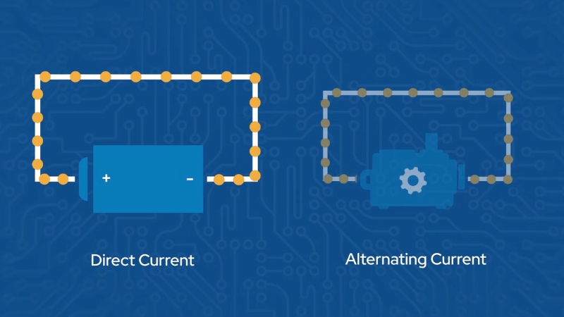
DC and AC look similar when measured by avoltmeter, number on a display, but they behave very differently. DC flows steadily in one direction, supplying constant voltage and current.
AC repeatedly reverses direction, and its voltage oscillates sinusoidally. These differences have profound effects on everything from power transmission to electronics design.
Property
Direct Current (DC)
Alternating Current (AC)
Flow direction
Electrons move in a single direction from the positive to the negative terminals.
Current repeatedly reverses direction, oscillating between positive and negative.
Voltage behaviour
Voltage is steady; there is no intrinsic frequency or phase shift.
Voltage varies sinusoidally; standard household mains oscillate 50–60 times per second.
Ease of transformation
Changing voltage requires DC‑DC converters or motor‑generator sets; stepping DC up or down is complex.
Voltage is easily changed using transformers, enabling efficient long‑distance transmission.
Typical sources
Batteries, photovoltaic modules, fuel cells, and electronic circuits.
Electrical grid, generators, and alternators are used by most household and industrial equipment.
Voltage levels
Usually low (5–24 V) in consumer electronics; battery banks may reach 48 V or more.
Highdomestic supplies range from 100–240 V; transmission lines operate at thousands of volts.
Applications
Portable devices, LED lighting, digital electronics, DC motors, and energy storage.
AC motors, HVAC systems, refrigerators, lighting, grid tie‑in, and industrial machinery.
Advantages
Provides a constant, stable supply; no reactive components; ideal for electronics.
Easily transformed; efficient transmission; zero crossing enables safe switching.
Disadvantages
Difficult to interrupt; voltage conversion is inefficient and complex; it suffers from electrolytic corrosion in conductors.
Peak voltages are higher than the RMS value; reactive components cause phase shifts; requires insulation against peaks.
DC’s constancy makes it ideal for powering electronic circuits and charging batteries. There is no frequency to worry about, and there is no reactive power; current and voltage are always in phase.
However, DC does not lend itself to long‑distance transmission because its voltage cannot be easily changed; stepping it up requires expensive converters, and switching it off can cause dangerous arcing because the current never naturally falls to zero. AC, by contrast, is naturally suited for distribution.
The sinusoidal waveform crosses zero every cycle, making it easy to interrupt power safely; transformers can step it up to high voltages to minimise line losses and then step it down again for consumers. AC’s drawback is that its voltage is continuously changing, so equipment must be designed to handle peaks that exceed the RMS voltage.
Capacitors and inductors store energy and cause phase shifts, producing reactive power that complicates power factor correction and system design. Thus, while AC dominates grids, DC remains vital inside devices and storage systems, necessitating a reliable method to convert between the two.
How Inverters Transform DC into AC
An inverter performs the sophisticated task of transforming unidirectional DC into bidirectional AC at the required voltage and frequency. Early inverters used mechanical switches, electromagnetic contacts that reversed the battery connections rapidly, producing a crude square wave.
Modern inverters are entirely electronic; they employ transistors, microcontrollers, inductors, and capacitors to synthesise a clean sine wave. While designs vary, most inverters follow the same sequence of operations:
Stage
Function
Key Components and Operation
Boost (DC–DC conversion)
Increases the low battery voltage to the desired AC peak voltage.
A switching regulator or transformer steps up voltage while regulating current. For instance, a 12 V battery must be boosted to about 160 V DC to generate 115 V RMS AC.
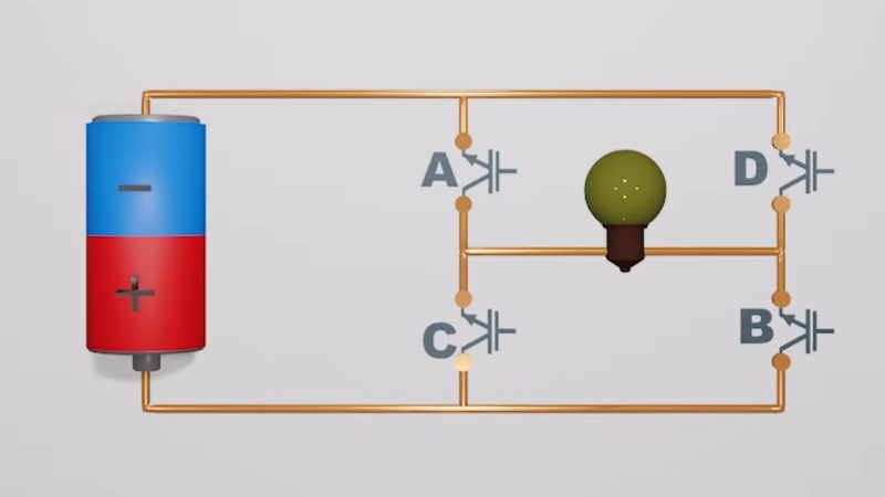
H‑bridge switching
Alternates the polarity of the boosted DC to create an alternating waveform.
Four transistors arranged in an H‑bridge connect the positive and negative DC rails to the AC output in opposite orientations, producing a square wave at the desired frequency.
Pulse‑width modulation (PWM)
Shapes the square wave into an approximation of a sine wave.
A microcontroller rapidly switches the H‑bridge on and off with varying duty cycles; by adjusting the width of each pulse within a cycle, the average output voltage follows a sinusoidal profile.
Filtering (LC smoothing)
Removes high‑frequency switching noise and produces a smooth AC waveform.
The pulsed output passes through a low‑pass filter composed of inductors (L) and capacitors (C); this resonant circuit attenuates the high‑frequency components, leaving a clean sine wave similar to grid power.
Modern inverters rely on sophisticated electronics to convert DC into AC efficiently and reliably. The first stage, DC–DC conversion, is essential because most storage systems operate at low voltages.
Boost converters or transformers temporarily store energy in magnetic fields to raise the voltage before releasing it on the output side. This ensures the subsequent H‑bridge has enough headroom to generate the desired AC amplitude.
The H‑bridge is the heart of inversion. Four switching devices, transistors or IGBTs, connect the positive and negative rails to either end of the output.
By switching diagonally opposite transistors, the H‑bridge inverts the polarity of the DC supply, yielding a square wave whose period equals the desired AC frequency. Early inverters stopped here, producing abrupt transitions that created large harmonic content and were only suitable for robust resistive loads.
To approximate a sine wave, the inverter must vary how long each half‑cycle is applied. Pulse‑width modulation accomplishes this by dividing each cycle into many small segments; within each segment, the switch is on for a variable fraction of the time.
Narrow pulses near the zero‑crossings and wider pulses near the peaks cause the average voltage to trace a sinusoid. A control microcontroller calculates the appropriate pulse widths hundreds or thousands of times per second.
PWM also allows the inverter to regulate both output voltage and frequency precisely. By changing the duty cycle or switching frequency, the same hardware can produce 120 V 60 Hz or 230 V 50 Hz AC as required.
Finally, the LC filter smooths the stepped PWM output. Inductors resist changes in current, while capacitors resist changes in voltage; together they attenuate high‑frequency harmonics and allow only the fundamental sinusoidal frequency to pass.
The result is a pure sine wave with minimal distortion. High‑quality inverters may use multi‑stage filters to further reduce total harmonic distortion (THD). Each stage introduces some losses, which is why pure sine‑wave inverters typically have slightly lower efficiency than simpler designs.
However, the benefit, a waveform nearly identical to grid power, makes them essential for sensitive electronics.
Types of Inverter Waveforms
The type of AC waveform generated by an inverter determines what kind of loads it can power safely. Three common categories dominate the consumer market: square wave, modified sine wave, and pure sine wave. They differ in cost, complexity, and compatibility.
Waveform Type
Generation Method
Characteristics and Applications
Pros and Cons
Square wave
An H‑bridge alternately connects the positive and negative DC rails without varying pulse width.
Produces a rectangular waveform with abrupt transitions; suitable for simple resistive heaters or incandescent lamps.
Pros: inexpensive and efficient; minimal circuitry. Cons: high harmonic content; can overheat motors and cause buzzing or malfunction in electronics.
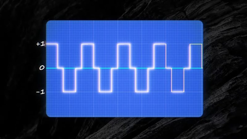
Modified sine wave
The H‑bridge output is switched at high frequency using PWM; discrete voltage steps approximate a sine wave.
Waveform resembles a staircase; acceptable for many appliances and power tools.
Pros: lower cost than pure sine; better compatibility than square wave. Cons: still contains harmonics that may cause audio hum or reduce efficiency in motors.
Pure sine wave
The modified sine wave passes through an LC filter to smooth out steps.
Output closely matches the smooth sinusoid delivered by the grid; THD is low.
Pros: compatible with all electronics, including medical devices, audio equipment, and variable‑speed motors; minimal interference. Cons: higher cost and slightly lower efficiency due to filtering components.
Analysis
Waveform quality matters because appliances are designed around the shape of the AC supply. A square wave inverter toggles the polarity of the supply abruptly, delivering full positive voltage and full negative voltage with no transition.
These sudden changes contain high‑frequency components that cause issues in inductive loads such as transformers and motors, leading to heat and noise. Basic heaters and incandescent lamps, which respond only to the RMS voltage, may tolerate square waves, but most electronics will not.
Modified sine‑wave inverters use PWM to subdivide each half‑cycle into small pulses whose average value approximates a sine. This reduces harmonic content and works adequately with devices like microwaves, refrigerators, and simple motors.
However, the discrete steps can still generate audible hum in audio equipment, interference in radio receivers, rs and inefficiencies in AC motors.
Pure sine‑wave inverters go one step further: they filter the PWM output through inductors and capacitors to generate a waveform nearly indistinguishable from grid power. Because the waveform crosses zero gradually, these inverters prevent the electromagnetic interference and overheating that plague other designs.
They are essential for sensitive electronics, medical devices, variable‑speed drives, and modern appliances with active power factor correction. Their added cost and slightly lower efficiency stem from extra components and higher design complexity, yet their clean output makes them the gold standard for home and industrial use.
Why DC‑to‑AC Conversion Is Necessary
Modern energy systems produce or store DC because it is easy to control and store. Solar panels output DC, batteries charge and discharge DC, and many electronic devices run internally on DC rails. Yet our homes and electrical infrastructure rely on AC.
The reason is historical and practical: AC can be transmitted at high voltage with low losses and then stepped down for safe consumer use. Most appliances and tools are designed to work with a 120 V or 240 V sinusoid.
If DC were fed directly into an AC appliance, the device might overheat or fail because its circuits expect alternating polarity and frequency. For example, induction motors rely on alternating magnetic fields to produce torque; DC would simply energise the coils without rotation.
Inverters allow renewable‑energy systems and battery‑backup setups to integrate seamlessly with AC‑based equipment. Without an inverter, off‑grid solar systems would have to rely exclusively on DC appliances, limiting their usefulness.
An inverter boosts the battery voltage, alternates the polarity, and shapes the waveform so that AC loads cannot distinguish the source from the grid.
When connected to a building’s wiring through a transfer switch, the inverter supplies power during outages or enables off‑grid living. Many modern inverters also act as uninterruptible power supplies (UPS), instantly switching from grid to battery during an outage so that computers and medical equipment continue running.
In essence, DC‑to‑AC conversion is what makes renewable energy and storage practical for mainstream use.
Selecting an Inverter: Specifications and Comparisons
Not all inverters are created equal. Selecting the right unit requires balancing power needs, input voltage, waveform quality, efficiency,y and special features.
The table below compares five representative inverters that span different sizes, waveforms, ms, and applications. Values are drawn from manufacturer specifications and technical documents to provide a fair comparison.
Model
Waveform
Continuous / Surge Power
Input Voltage & Efficiency
Key Features
Renogy 1000 W (RNG‑INVT‑1000‑12V)
Pure sine wave
1000 W continuous, 2000 W surge
12 V DC input; >90 % efficiency
Includes remote control and cables; low no‑load draw (<1 A); suitable for RVs, boats, and small backup systems.
Renogy 2000 W (RNG‑INVT‑2000‑12V)
Pure sine wave
2000 W continuous, 4000 W surge
12 V DC input; efficiency >90 %
THD <3 %; comes with remote and cables; one‑year warranty; good for medium off‑grid cabins and appliances.
Krieger KR1500
Modified sine wave
1500 W continuous, 3000 W surge
12 V DC input; up to 90 % efficiency
LCDs voltage and load; wired remote and ANL fuse kit included; cost‑effective for non‑sensitive loads.
Giandel PS‑2000KAR
Pure sine wave
2000 W continuous, 4000 W surge
24 V DC input; ~90 % efficiency
15 ft wired remote; LED indicators; multiple protections against over‑voltage, temperature, and overload; suitable for boats and off‑grid homes with 24 V banks.
Growatt SPF 3000TL
Pure sine wave
3000 W continuous, 6000 W surge
48 V DC input; ~90 % peak efficiency
Hybrid inverter with integrated MPPT charge controller; configurable AC/solar priority; Wi‑Fi monitoring; scalable parallel operation up to 18 kW; ideal for larger off‑grid or hybrid systems.
Small pure‑sine units (Renogy 1000 W and 2000 W): Renogy’s 1000 W model is compact yet capable of powering laptops, televisions,s and small appliances. Its low quiescent current (<1 A) preserves battery life, and its remote control allows convenient operation in RVs or boats.
The 2000 W version doubles the power, enabling it to run refrigerators, power too, ls or multiple devices simultaneously. Both models maintain high efficiency (>90 %) and produce clean sine waves, making them safe for sensitive equipment.
Modified‑sine option (Krieger KR1500): The Krieger unit offers a lower‑cost alternative with modified sine‑wave output. Its 1500 W rating and 3000 W surge capacity cover many basic appliances, and the integrated LCD provides real‑time status.
However, because it does not filter the waveform to a pure sine, it may cause audible noise in audio equipment and is less suitable for medical devices or variable‑speed motors. It is best used for resistive loads, power tools, and non‑critical applications.
Medium pure‑sine inverter (Giandel PS‑2000KAR): This 24 V unit targets systems with larger battery banks. Operating at a higher input voltage halves the current for a given power, reducing cable losses.
Giandel’s inverter delivers a pure sine wave with around 90 % efficiency and includes protections against high and low voltage, over‑temperature, and overload. A long remote cable and LED display simplify installation in boats or cabins.
View this post on Instagram
Hybrid inverter (Growatt SPF 3000TL): Growatt’s 3 kW unit goes beyond simple inversion. It integrates an MPPT solar charge controller, an AC transfer switch,h and the ability to prioritise solar or grid input. Its 48 V input reduces conductor currents and improves efficiency.
For larger systems, several units can be connected in parallel to achieve up to 18 kW capacity. The built‑in Wi‑Fi lets users monitor performance remotely. Because it produces a pure sine wave, it can power everything from pumps and air‑conditioners to computers and is well-suited for off‑grid homes or hybrid battery‑backed systems.
When choosing an inverter, evaluate not just the continuous power rating but also surge capability, waveform quality, input voltage, efficiency, and feature set. Higher input voltages (24 V or 48 V) minimise current, reducing wire size and losses.
Pure sine‑wave units are necessary for sensitive electronics, while modified or square‑wave units may suffice for resistive loads. Hybrid inverters with integrated charge controllers simplify solar installations.
Finally, consider certifications and warranties; reputable brands specify total harmonic distortion (THD) and stand behind their products with clear warranty terms.
Practical Considerations for Integrating Inverters
Selecting an inverter is only the beginning; integrating it into a system requires considering battery capacity, safety, and load management:
- Sizing the battery bank: The inverter’s power rating dictates how much current it draws from the battery. For a 12 V inverter supplying 1000 W, the current draw is roughly 83 A (1000 W / 12 V). Larger systems may benefit from 24 V or 48 V banks to halve or quarter the current, reducing copper losses and allowing thinner cables. Ensure your battery bank can sustain the peak current without excessive voltage sag.
- Surge loads: Many appliances, refrigerators, pumps, and power tools draw several times their rated power when starting. Choose an inverter with adequate surge capability and ensure the battery can supply the surge current. The table above shows surge ratings twice the continuous rating for most units.
- Efficiency and standby consumption: Inverters consume some power even when no load is attached. Low no‑load draw (e.g., <1 A) prolongs battery life in standby mode. Pure‑sine units may have slightly lower efficiency than modified‑sine units because of filtering losses, but the difference is minor compared to the benefits of clean power.
- Safety and protection features: Look for over‑temperature, over‑voltage, under-voltage,e and overload protections. Ground‑fault circuit interrupter (GFCI) outlets enhance safety. Remote controls and displays make monitoring easier.
- Location and cooling: Inverters generate heat. Install them in a well‑ventilated area away from flammable materials. Some units include fans or heat sinks to maintain temperature under load.
Conclusion
@mrarduino Replying to @ronaldrono52 yes it’s possible!#electronics ♬ original sound – Mr. Arduino
DC‑to‑AC conversion is the cornerstone of modern renewable‑energy systems and backup power solutions.
While DC is the natural output of batteries and solar panels, our homes and devices are built to accept AC because AC is easily transmitted and transformed.
Inverters perform the essential task of boosting low‑voltage DC, alternating its polarity, and shaping it into a sinusoidal waveform.